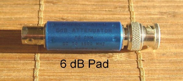
Here is a way that a PRO-2026 scanner may be used for tuning cavity filters when used in conjunction with a good signal generator. To start, check to see if the gain is reasonably flat. I checked the sensitivity between 440 and 450 MHz in 1 MHz steps. The worst case was at 450 MHz where the sensitivity was -106 dBm for 12 dB SINAD with a 6 dB 50 Ohm pad at the antenna input of the scanner and -107.7 dBm at 440 MHz. The other frequencies fell between these two. The 6 dB pad is used to mask any impedance mismatch caused by the scanner input. I also checked it between 140 and 150 MHz in 1 MHz steps. The worst case was -106.7 dBm and the best was -107.2 dBm. The tests can be done using the 12 dB SINAD method or with an AC voltmeter an the quieting method. The above information is used if you want to sweep (plot) the device under test.
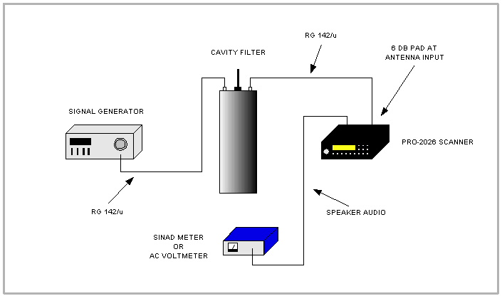
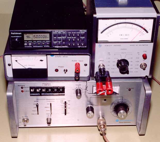
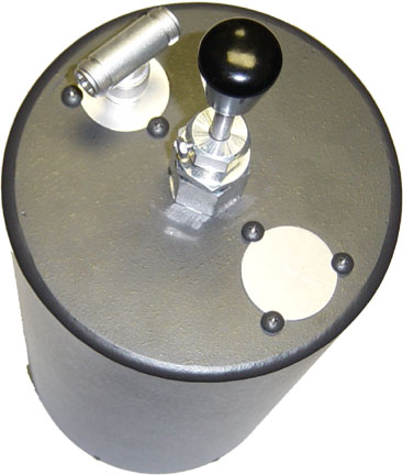
Here is the layout and a photo of the equipment I used to check a cavity filter. I measured a VHF Sinclair quarter wave pass cavity at 145 MHz configured for 0.5 dB insertion loss. The results tracked closely with the published response curve. The tests involve first determining the scanner sensitivity either with the SINAD or quieting method as above. This is the reference level. The cavity is then placed between the generator and scanner and measurements are made on the frequencies of interest. The signal generator level is adjusted to keep it at the reference point initially obtained. The difference in the required level is the isolation provided by the cavity. My preferred way of doing these tests is the 20 dB quieting method.
I also tuned up a Sinclair UHF reject filter using this set up. The readings were then compared to measurements using all professional equipment and the readings agreed within a few tenths of a dB.
It is importance that a good signal generator with low case leakage be used. That is, the signal should only come out of the RF connector on the generator and not radiate out of the case. Also, good quality RF cables should be used. Any leakage before the device being tested or leakage from the device itself may get into the scanner after the antenna connector. This will limit the range of the measurements. The scanner is not shielded. I have not determined at what level leakage would be a problem in my particular set-up. It may also be necessary to use a regulated power supply to power the scanner to insure the hum level at the audio output is low enough to get a suitable reading on the meter.
It may be possible to substitute a typical VHF/UHF Ham transceiver in place of this scanner.
The above method is not the best way to tune or check cavities or duplexers but it works. I have measured cavity filter isolation of up to 87 dB without a problem.